
Performance Measurement of Thermoelectric Modules
By Dr. Jeff Hershberger, Staff Scientist
Summary
This white paper explains how thermoelectric modules (TEM/TECs) undergo performance testing to verify cooling capacity; temperature difference (temperature differential, ΔT = Th − Tc); maximum temperature differential (ΔTmax at Qc = 0); cold-side heat load (Qc); maximum heat load (Qmax at ΔT = 0); and efficiency (COP = Qc/(V × I)). The paper identifies three test challenges—sensor-to-surface thermal resistance, wire heat conduction, and ambient heat transfer—and examines solutions. It also describes customer requirements considered during testing.
Structure and Basic Functions of Thermoelectric Modules
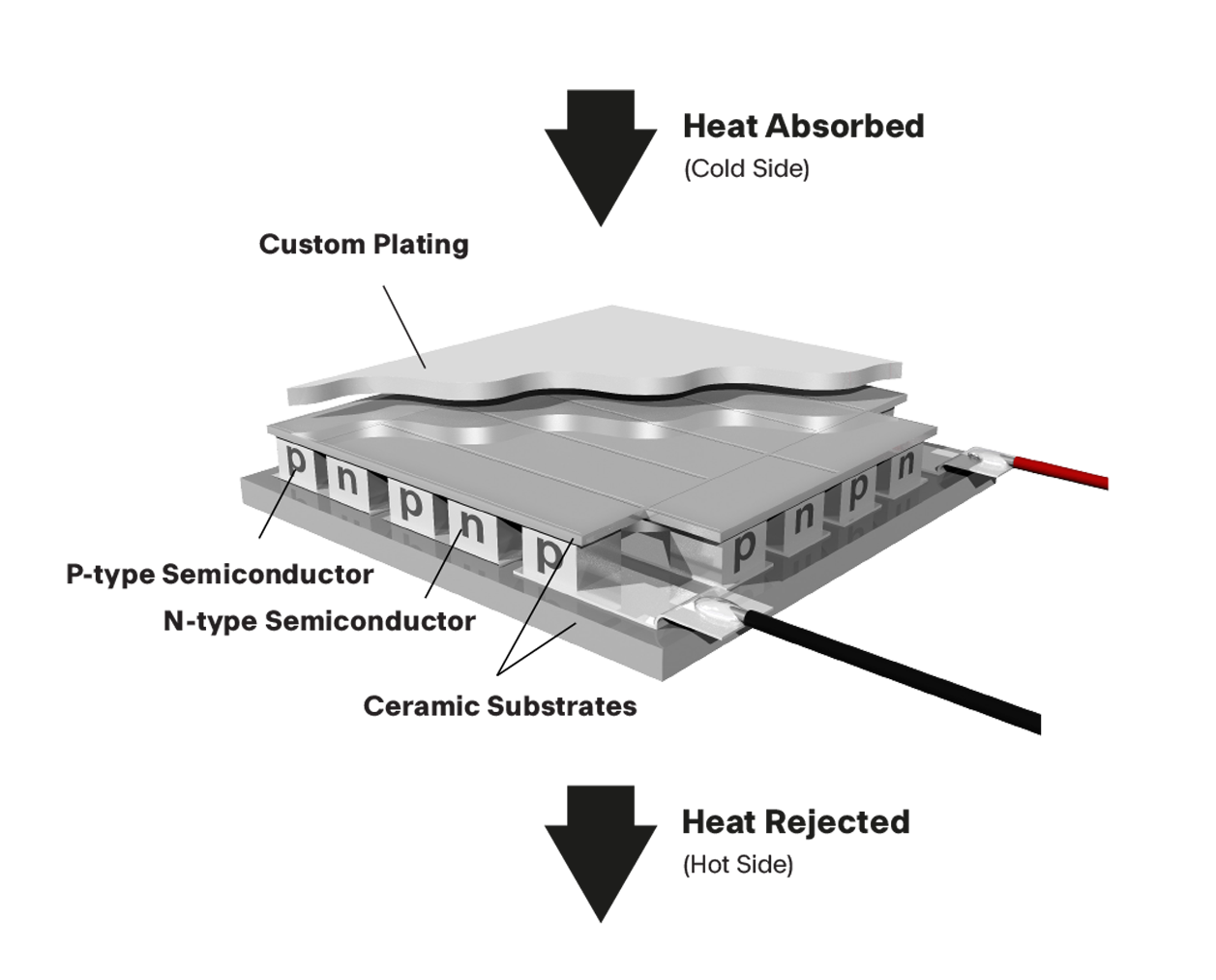 A thermoelectric module ("TEM") or cooler ("TEC") is an electronic device used for temperature control. The top face of the TEM is often referred to as the "cold side" or "controlled side," while the bottom face is called the "hot side". A TEM is powered by DC electricity and has two terminals, positive and negative. Internally, a TEM contains many pieces of P and N semiconductor ("elements" or "dice") soldered together electrically in series.
When a positive DC voltage or current is applied to a TEM's positive terminal, two things happen: the top face gets colder, and heat comes out the bottom face. In a user's application, the heat coming out of the bottom face is removed by a heat sink, liquid cold plate, or other heat exchanger.
Temperature differential and how to measure it
When DC current is applied to the TEM, the temperature difference created between the cold side and hot side is called "DeltaT" or "DT". Three physical effects create this DT: Peltier heat pumping, resistive heating inside the TEM, and heat flow back from the hot side to the cold side through the semiconductor dice.
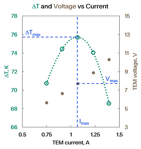
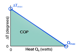
The result is that a steady DT is formed across the TEM, and heat (equal to voltage times current) comes out the bottom. As the DC current rises, DT increases until it reaches a maximum called DTmax. If power is increased past this point, DT will decrease. It is important to note that in practice, DTmax only occurs if there is no external heat load on the cold side of the TEM. In the next section, we will discuss heat pumping of such external heat loads. ( Figure 1)
To measure DTmax, we mount the TEM on a heat exchanger and hold that heat exchanger at a desired constant hot side temperature ( Th ). Then we increase the DC current while measuring the changing cold side temperature ( Tc ). This corresponds to the green circles in the plot in this section. We find the current where DTmax is largest, and we call that current Imax. We call the voltage at that condition Vmax.
Heat pumping and how to measure it
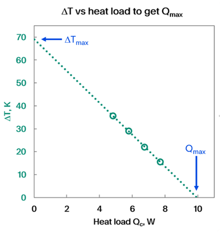
An external heat load applied to the cold side of the TEM is called Qc. Putting a heat load on the TEM warms the cold side, so DT is smaller. Every TEM has a maximum heat load it can pump, called Qmax, and this is defined as the heat load that causes DT=0.
A TEM designer can create a TEM with a larger Qmax by increasing the number of semiconductor dice. However, a TEM with more dice does not have a larger DTmax. In addition, higher Qmax is not necessarily better for efficiency, which we will discuss below. (Figure 2)
To measure Qmax, we mount the TEM on a heat exchanger at a controlled Th temperature and begin by measuring DTmax. We do that because we need to know Imax. Next, we apply a constant current Imax to the TEM. We then increase the heat load Qc while measuring DT. Low heat loads will give larger DT values and vice versa; the measured values are shown as green circles in the plot. We calculate the Qc that would create DT=0, and that value is Qmax.
Challenges and Approach
Challenges in performance testing
To measure DTmax and Qmax, we need to know the temperatures at the top and bottom faces of the TEM and the amount of heat entering the top face. Three challenges make it difficult to learn Tc, Th, and Qc accurately: 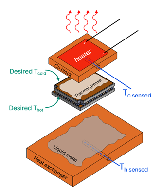
- First, we cannot directly measure the temperatures of the faces of the TEM because our temperature sensors are located in copper blocks. There is some thermal resistance between the temperature we sense and the temperature we want to know.
- Second, wires are needed to sense temperature and to power the heater, and these wires conduct heat to or from the cold side of the TEM. This is a major problem if the wires are at room temperature, but Tc is very cold, for example during a DTmax experiment. We try to apply a specific heat load (the heater voltage times its current), but the wires add or subtract an unknown amount of heat from our test.
- Third, air carries heat. Conduction, convection, and radiation all allow heat to enter or leave the cold side of the TEM. These effects also add or subtract an unknown amount of heat from Qc.
Approach to the performance testing challenges
In our performance testing system, we can improve the accuracy of measured Tc and Th by using the best available thermal interface materials between the TEM and the copper blocks that contain the sensors. Thermal greases are commonly used for this purpose. However, liquid metal alloys can provide thermal resistance one-fifth to one-fourth the thermal resistance of grease. These alloys are liquid at room temperature, like mercury.
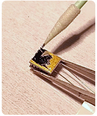
The photo to the right shows liquid metal being applied to the bottom of a TEM. Unfortunately, liquid metal cannot be used on the cold side of a TEM, because the cold side will reach temperatures far below the freezing point of any liquid metal alloy.
Conduction of heat through wires can be minimized by making sure that the wires are not warmer or colder than the cold side of the TEM. Normally, these wires are connected to a power supply or other electronics. However, we can cool the wires by laying them across a cold surface near the TEM we are testing. Our approach is to place a second TEM, called the "control TEM", next to the TEM we are testing. The cold side of the control TEM is held at the same temperature as the tested TEM, so the wires don't interfere with the test. A schematic side view of this arrangement is shown below.
Wire Testing Arrangement - Schematic Side View
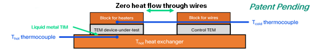
Conduction of heat through the air around the TEM, convection, and condensation of humidity onto the TEM can all be eliminated by performing the test in a vacuum environment. We use a bell jar and a high vacuum system to reach pressures lower than 0.13Pa (about 10-6 atmosphere).
Objectives and Customer Requirements
Objectives of Thermoelectric Module Performance Testing
One objective of performance testing is to verify that prototype TEMs will meet a customer's requirements. This testing provides measurement data to support the TEM designer's calculations.
Another objective is to verify that a specific shipping lot of TEMs ordered by the customer meets requirements. This is done to satisfy lot acceptance requirements for customers whose incoming quality control requires measurement data.
In either case, the requirements provide pass-fail criteria for the test results.
Types of Customer Requirements in TEM Performance Evaluation
Different customers request different types of performance testing data. One type of pass-fail criteria is to meet a minimum DTmax and Qmax at a specific temperature Th. These minimums could come from the customer's application or they could be a simple verification of the TEM designer's calculations.
A second type of pass-fail criteria is to measure the TEM's power consumption or efficiency in a simulation of the customer's application. The customer provides a specific Th, Tc, and Qc, and the performance test measures the amount of power (voltage times current) consumed by the TEM to maintain those conditions. Efficiency, or Coefficient of Performance (COP), is defined as the heat pumped divided by the power consumed: COP = Qc/V*I.
It is very important to understand the customer's use conditions in detail. Specifying Th, Tc, and Qc may sound simple, but it is easy to miss minor contributions such as wires to and from the items on top of the TEM, the heat load not being uniformly distributed across the TEM, high thermal resistance outside the TEM causing all temperatures to rise, etc. In addition, the customer may have constraints on how much current or voltage can be delivered by their power supply.
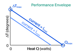
These two types of customer requirements are illustrated in the Performance Envelope Figure 1, which is similar to the plot of DT and Qc shown in the previous section "Heat pumping and how to measure it". The blue circles represent the DTmax and Qmax calculated by the TEM designer, whereas the green shaded area represents all the combinations of Qc and DT that the TEM can provide. In this green area, called the "performance envelope", COP can be measured.
Interpreting TEM Performance Envelope
The performance of a TEM under a heat load is similar to the way a fan or a water pump responds: if you ask for more flow, you get less pressure. In a TEM, the relationship between DT and Qc is linear, as seen in the previous section "Heat pumping and how to measure it". The line between DTmax and Qmax is what the TEM provides when it is powered by a current equal to Imax. On that line, the efficiency is poor, because the TEM is working as hard as it can.
However, if the TEM current is less than Imax, then performance is still linear but with lower combinations of DT and Qc. See the lighter of the two blue lines in Figure 2. Efficiency is better if the Th, Tc, and Qc can be supported with current less than Imax.
It is tempting to think that you can make the efficiency as high as you want by designing a TEM with very large Qmax so it operates at very low current to support the Qc. However, when designing a TEM, there is an optimum efficiency for a specific Th, Tc, and Qc. That is the best you can get.
TEM Efficiency COP: Definition and Test Method
We have defined COP as the heat load divided by the TEM's power consumption, COP = Qc/V*I.
Measurements are taken at customer-specified temperatures Th and Tc , using the same equipment that is used for measuring Qmax.
Results from an example COP test are shown in Figure 7. To set up the test, we raised the Th temperature to 65°C and turned on the heater's power supply to apply a heat load of 2.75 Watts.
Then we turned on the TEM's power supply to deliver a specific current, and we measured Tc. That gave us DT, which is shown on the plot as the brown circles corresponding to the Y axis on the right.
At the same time, we measured the TEM voltage and combined it with the TEM current to get power consumption (green circles, corresponding to the left Y axis).
We repeated the above measurements for five different values of TEM current, giving five pairs of green/brown circles. In this case the customer's requirement was DT = 30K, which was between two of our measurements. We used curve fits (dotted lines) to estimate the current that would give DT = 30K, and the power consumption at that condition. In this case, the power consumption was 2.84 Watts, which gave us a COP of 0.96.
Equipment for Performance Testing at TTS
 The techniques described in the above section "Approach to the performance testing challenges" were first used in a reference/development test system. In this test system, the "control TEM" is powered by a different power supply from the TEM being tested and it is controlled independently. This provides high accuracy because the temperatures of the TEM being tested and the control TEM match exactly. However, it has low throughput because it takes a long time for each data point to thermally stabilize.
A production tester has been built where the "control TEM" is powered by the same power supply as the TEM being tested, and is of the same design as the TEM being tested. As a result, the temperature of the control TEM is close to the temperature of the TEM being tested, giving adequate accuracy. The throughput of this test system is higher because thermal stabilization is faster.
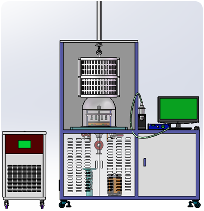
The rendering to the right illustrates a typical test system’s component: bell jar with lift, water chiller, vacuum pumps, and computer system with power supplies.
Frequently Asked Questions (FAQ)
What is a TEM (or TEC)?
A DC-powered device composed of many P and N semiconductor “dice” in electrical series that pumps heat from the cold side to the hot side when current is applied.
What is ΔT and ΔTmax?
ΔT is the temperature difference between the hot and cold sides. ΔTmax is the maximum ΔT, which occurs only when there is no external heat load (Qc = 0) on the cold side.
How do you measure ΔTmax of thermoelectric coolers?
Mount the TEM to a heat exchanger, hold Th constant, sweep current, measure Tc, and find the current where ΔT peaks (Imax). The corresponding voltage is Vmax.
What is Qc and what is Qmax?
Qc is the external heat load applied to the cold side. Qmax is the load that makes ΔT = 0—the maximum heat the module can pump at the specified Th.
How do you measure Qmax?
First determine Imax from the ΔTmax test. Then run at I = Imax, increase Qc while recording ΔT, and extrapolate to ΔT = 0; that Qc is Qmax.
Does increasing the number of dice improve ΔTmax or efficiency?
More dice can increase Qmax but does not increase ΔTmax; higher Qmax is not necessarily more efficient.
How are thermoelectric modules (TEM/TECs) performance-tested?
Defines/measures ΔT, ΔTmax, Qc, Qmax, Imax/Vmax, and COP = Qc/(V×I) at fixed Th.
Are all modules “performance-tested,” and how?
We only test samples of a design or of a production lot. Not every part number is checked in performance testing.
What affects accuracy and efficiency?
Challenges: sensor placement, wire heat conduction, and ambient exchange; mitigations: high-conductivity interfaces, control TEM, vacuum < 0.13 Pa.
Acronyms & Symbols
|
|
|
|
|
|
|
|
|
|
|
|
|
|
|
|
|
|
|
|
|
|
|
|
|
|
|
|
|
|
|
|
|
|
|
|
|
|
|
|
|
|
|
|
|
|
|
|
|
|
|
|