Beating the Heat at the Handle: Cable and Connector Cooling for High-Power EV Charging
Liquid cooling for high-power charging (HPC), heavy-duty truck, and Megawatt Charging System (MCS) cables, from Tark Thermal Solutions
Summary
Liquid cooling becomes mandatory for EV charging cables above approximately 400 A, roughly the point where chargers exceed 300 kW, because the cable and connector interface is the highest heat-flux point in the entire charging path and air cooling reaches its practical limit near 400 A. Tark Thermal Solutions designs and manufactures the closed-loop water-glycol and dielectric-oil cooling units that remove this heat.
Typical design envelope for a cable and connector cooling unit:
| Parameter | Typical value |
|---|---|
| Cooling capacity, per cable | 1–3 kW (up to ~5 kW for continuous-duty and MCS applications) |
| Coolant flow rate | 2–3 L/min |
| Operating pressure | 1–4 bar |
| Cable current range served | 500–700 A Combined Charging System (CCS); up to 3,000 A (MCS specification ceiling) |
| Ambient operating temperature | −30 °C to +55 °C |
| Ingress protection | IP54 to IP56 |
| Mechanical impact protection | IK10 (20 joule impact, per IEC 62262) |
| Acoustic emissions | ≤65 dB(A) |
| Coolant medium | Water-glycol (mainstream) or dielectric oil (high-current) |
| Telemetry | Temperature, flow, and pressure sensors; CAN bus interface; OCPP 2.0.1-ready |
| Design life | >10 years station life; cable sets rated ~10,000 plug cycles |
Introduction: why the cable and connector became the thermal bottleneck
EV charging infrastructure is no longer a single market. It has separated into three segments with materially different thermal requirements:
- Passenger-vehicle high-power charging (HPC) - 150–350 kW
- Heavy-duty truck charging - 350–500 kW
- Megawatt Charging System (MCS) - 500 kW to 1 MW and above
The European and North American market for EV-charging liquid-cooling systems is projected to grow from approximately 73,000 units in 2025 to approximately 680,000 units by 2035, a compounded annual growth rate of roughly 25%. Cable cooling is expected to account for approximately 85% of that market, as heavy-duty truck charging scales alongside continued HPC and MCS deployment.
As charging power and current density rise while connector sizes remain unchanged, cable and connector thermal management has stopped being a supporting design consideration. It is now a core enabler of charging speed, safety, station uptime, and user experience.
For charger OEMs, charge point operators (CPOs), and subsystem suppliers, cable and connector cooling must accomplish four things:
- Remove heat efficiently at the cable-to-connector interface, the highest thermal loading point in the charging path
- Maintain reliability in unprotected outdoor environments across a −30 °C to +55 °C range
- Keep acoustic emissions at or below 65 dB(A) for urban and destination installations
- Minimize field-service events across a station life exceeding 10 years
This application note covers where heat is generated in the cable and connector assembly, why liquid cooling becomes non-optional at high power, and what system designers should specify when selecting or developing a cooling solution.
What is liquid-cooled EV charging cable cooling?
Liquid-cooled EV charging cable cooling is a closed-loop thermal management system that circulates coolant through channels running alongside or in direct contact with the high-current DC conductors inside a charging cable, carrying resistive heat away from the cable and connector to a liquid-to-air heat exchanger in the dispenser or power cabinet.
The alternative, increasing conductor cross-section to reduce resistance, produces a cable that is too heavy and stiff for an operator to handle. Liquid cooling allows a thinner, more flexible cable to carry current that would otherwise require an unmanageable conductor size. This is the core engineering trade the technology exists to solve.
Where the heat comes from
A DC charging station converts grid AC into the DC the vehicle battery requires. Electrical losses along that path become heat, and the cable and connector represent one of the most thermally demanding areas because of:
- High-current DC conductors routed through a flexible, user-handled cable
- Cable-to-connector interfaces and DC contacts, where contact resistance concentrates heat
- Severely limited physical space inside the connector housing, restricting both conduction paths and coolant channel geometry
- Safety limits on touch temperature, because the handle must remain safe and comfortable during and immediately after a session
Cable and connector losses scale with the square of current, following I²R resistive heating. Doubling current quadruples heat generation. At the connector, heat concentrates further because contact resistance adds to conductor resistance in a space with almost no thermal mass and no room for a heat sink.
Why air cooling runs out
At lower power levels, passive or forced-air cable cooling is sufficient. As current rises, air cooling reaches limitations. Approximately 400 A is the practical transition point where air cooling becomes difficult to implement effectively in a compact cable and connector assembly. Passenger-vehicle HPC, heavy-duty truck charging, and MCS all exceed that threshold at their upper power ranges.
Expressed in power terms: above approximately 300 kW, liquid cooling of the cable is mandatory, not optional. Battery-buffered charging systems, whether all-in-one (AIO) or external, may include chillers or heat pumps for battery pack temperature management, but pack conditioning does not substitute for cable cooling.
How charging power drives cable and connector thermal demands
The appropriate cooling approach depends on charging power, duty cycle, ambient conditions, and application. The connector standard sets the electrical envelope.
 Combined Charging System (CCS) is the current mainstream DC fast-charging standard for passenger EVs and most of today's heavy-duty truck charging. It extends the AC Type 1 connector (CCS1, common in North America) or Type 2 connector (CCS2, common in Europe) with two additional DC contacts. CCS operates at up to 1,000 VDC and up to 500 A. Liquid-cooled cable assemblies in service today are commonly specified for the 500–700 A range.
Megawatt Charging System (MCS) is purpose-designed for heavy-duty applications. The MCS specification allows up to 1,250 VDC and 3,000 A, though early deployments target the 1 MW range. MCS is expected to become a major growth area after 2030, particularly for long-haul truck charging.
Cooling requirements by charging segment
| Charging segment | Typical power | Typical cable current | Cooling approach | Primary connector thermal concern |
| Passenger-vehicle HPC | 150–350 kW | 300–500 A | Liquid-cooled cable and connector assembly, typically water-glycol | Connector contact temperature; heat density in a compact handle |
| Heavy-duty truck charging | 350–500 kW | 500–700 A | Liquid cooling required for cable and connector, with particular attention to cooling connector contacts | High continuous current and connector hot spots under repeated heavy-duty cycles |
| Megawatt Charging System (MCS) | 500 kW–1 MW+ | 700 A and above | Multi-loop liquid cooling; advanced dielectric or immersion-style cable and connector concepts | Extreme current density, continuous-duty operation, and high heat rejection at the connector interface |
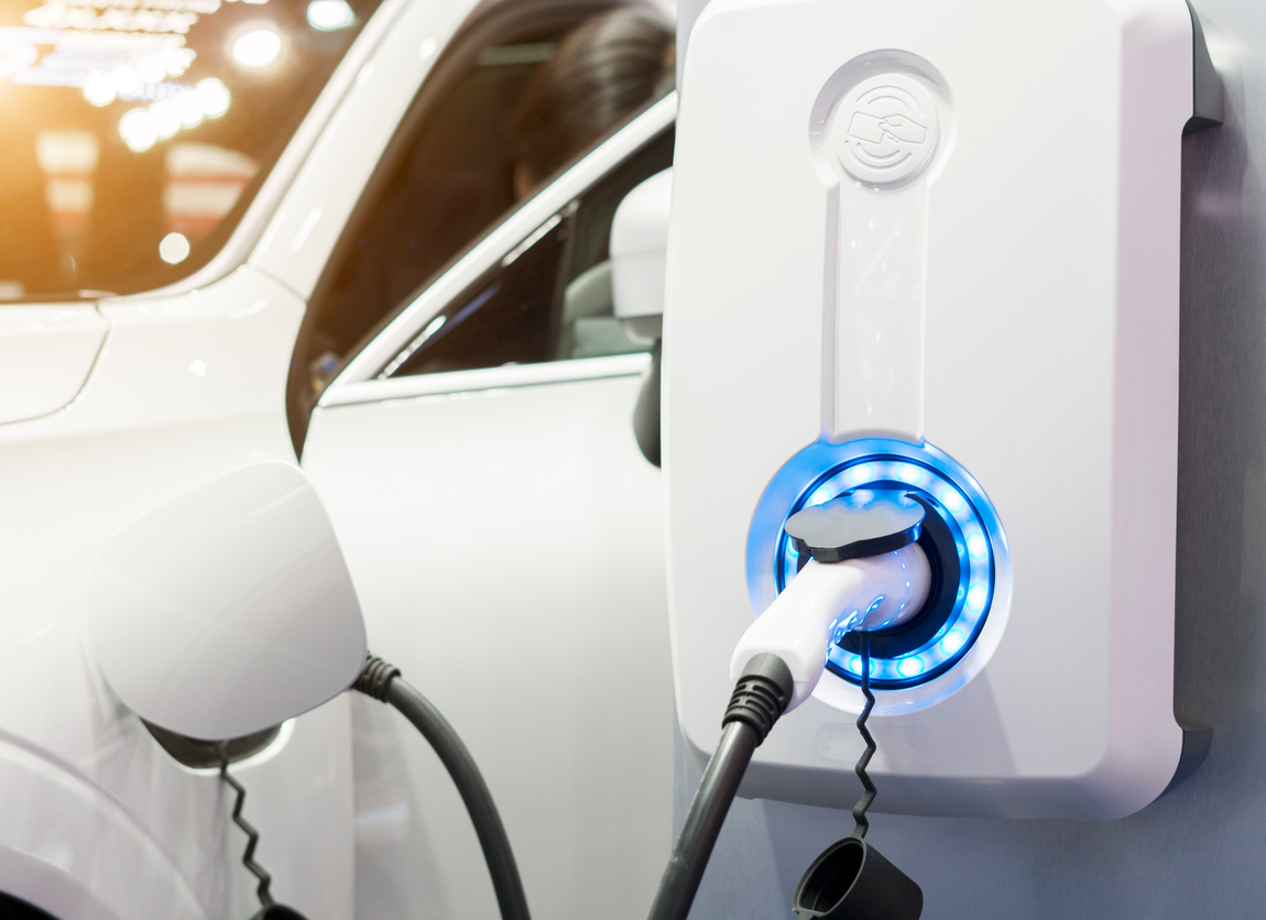 Passenger EVs increasingly use 800 V electrical architectures, which support faster charging at lower current than an equivalent 400 V design. This helps, but the parallel move toward 250–350+ kW charging still requires robust cable and connector cooling; the current reduction from higher voltage is outpaced by the power increase.
The split-cabinet trend and what it means for cooling
The charging industry is moving toward split-cabinet architectures, which concentrate power electronics in a central cabinet while keeping the dispenser slim. This raises achievable power density and improves serviceability, but it creates a specific thermal problem: heat must still be dissipated within the small dispenser and connector footprint, where there are now less enclosure volume and less airflow available for the cable cooling heat exchanger.
Split-cabinet designs therefore increase, rather than reduce, the engineering demand on a compact, high-capacity cable cooling unit.
Coolant selection: water-glycol versus dielectric oil
Closed-loop water-glycol systems are the mainstream solution for many passenger-vehicle HPC and heavy-duty truck cable designs. They circulate coolant through or near the current-carrying conductors and connector contacts, transferring heat to a liquid-to-air heat exchanger in the dispenser or charging cabinet. Typical nominal system parameters include 2–3 L/min flow, 1–4 bar operating pressure, IP54–IP56 environmental protection, and operation across approximately -30°C to 55°C ambient conditions.
Dielectric-oil cooling offers another path for the cable and connector at heavy-duty truck and MCS power levels. Because the fluid is electrically nonconductive, it may directly contact or immerse energized conductors within the cable and connector, improving heat transfer and reducing localized hot spots. This approach can support thinner, more flexible cables at high current, but introduces additional considerations involving fluid compatibility, sealing, service requirements, and environmental compliance.
What a liquid-cooled cable assembly contains
A typical liquid-cooled cable assembly integrates:
- High-current DC conductors
- Coolant supply and return paths
- Protective earth and communication lines
- Temperature sensors near the connector and other critical interfaces
- Multiple protective insulation layers and an external environmental jacket
- Seals, fittings, and mechanical strain-relief components
Cable and connector cooling architecture options
No single architecture is optimal for every charging segment. Selection depends on power level, target cost, required reliability, and system integration constraints.
| Cooling technology | Typical use | Key benefits | Design considerations |
|---|---|---|---|
| Water-glycol liquid cooling | Passenger-vehicle HPC and heavy-duty truck cable/connector assemblies | Mature technology, good heat transfer, well-controlled connector temperatures | Pumps, hoses, seals, coolant maintenance, leakage prevention |
| Refrigerant-assisted liquid cooling | Hot climates and high thermal loads at the connector | Higher temperature differential and stronger heat rejection | Greater integration complexity; refrigerant service requirements |
| Single-phase immersion cooling | Advanced heavy-duty truck and high-current MCS cable systems | High heat transfer, lower connector hot-spot risk | Dielectric fluid compatibility, fluid handling, sealing |
| Two-phase immersion cooling | Extreme-current MCS cable and connector applications | Very high heat-transfer potential at the connector | System complexity, vapor management, monitoring, safety validation |
For most passenger-vehicle HPC and heavy-duty truck designs, water-glycol liquid cooling offers the best balance of performance, technical maturity, and integration flexibility. For the highest-current heavy-duty truck and MCS implementations, dielectric-fluid approaches become more relevant wherever cable weight, flexibility, and connector thermal margin are the binding constraints.
System design considerations
Size the cooling capacity to duty cycle, not peak power
An effective cable/connector cooling system should be designed as part of the charger architecture, not added after power, packaging, and service decisions are fixed. The cooling system should match cooling capacity to the duty cycle. Peak charging power alone is not enough. The cable/connector cooling system must account for:
- Continuous versus intermittent high-current operation
- Simultaneous use of multiple dispensers sharing cable cooling infrastructure
- Site utilization rate and charging-session frequency
- Solar loading and local ambient conditions acting on the cable jacket and connector housing
- Enclosure airflow restrictions around the cable cooling heat exchanger
- Seasonal operating extremes
For example, a highway passenger-vehicle site may require sustained high-power cable cooling in warm weather, while a heavy-duty truck depot may prioritize robust cable/connector durability across many overnight sessions at lower cost. The same nominal charger rating can therefore create very different cable/connector thermal requirements across passenger-vehicle, heavy-duty truck, and MCS applications.
Monitor the critical thermal variables
Temperature, pressure, and coolant-flow sensors at the connector provide the operational data needed to protect equipment and maintain uptime. A sensor-equipped cooling system can detect degrading pump performance, a blocked heat exchanger, low coolant level, abnormal connector resistance, or an emerging connector hot spot before a fault causes an outage.
Current market deployments do not yet use predictive maintenance. That gap is an opportunity: integrating temperature, flow, and pressure sensors with CAN bus interfaces and OCPP 2.0.1 readiness offers clear differentiation and enables condition-based service strategies rather than fixed-interval or reactive maintenance.
Design for outdoor reliability
Cable and connector assemblies operate in unprotected environments. Designs must meet:
- Dust and water ingress protection, commonly IP54–IP56 (per IEC 60529)
- Mechanical impact resistance for the connector housing, commonly IK10 — a 20 joule impact rating under the IEC 62262 code system for protection against external mechanical impact
- Vibration resistance and cable flex durability
- Corrosion and salt-spray resistance, relevant for coastal and road-salt environments
- Stable performance from −30 °C to +55 °C ambient
- Acoustic emissions ≤65 dB(A), particularly for residential, urban, and destination installations
A reliable cooling system depends on far more than the heat exchanger. Pumps, hoses, seals, fittings, valves, sensors, cable jackets, electrical isolation, and controls must be qualified as an integrated system, because the failure modes that take stations offline are rarely in the heat exchanger itself.
Prioritize serviceability
Public charging infrastructure is expected to operate for more than 10 years, and cable or connector downtime directly reduces both customer satisfaction and operator revenue. Serviceability must be designed in, not retrofitted:
- Tool-less filter panels for routine access
- Quick-disconnect hose connections to isolate the coolant loop without draining the system
- Planned maintenance cycles for coolant, pumps, and cable sets
- Replaceable filters where applicable
- Diagnostic telemetry that lets a technician isolate a fault before arriving on site
Cable and connector durability must also account for repeated handling, vehicle drive-over events, bending, strain, connector drops, and approximately 10,000 plug cycles. This burden is most severe for heavy-duty truck fleets and MCS depots with high daily session counts.
Cable and connector cooling by segment
Passenger-vehicle HPC: 350 kW highway charger
In a 350 kW DC fast charger serving passenger EVs on a highway corridor, the cable and connector must manage high current while remaining a safe, ergonomic user interface. A typical configuration:
- Liquid-cooled CCS cable and connector assembly
- Water-glycol coolant loop with dedicated pump, reservoir, heat exchanger, and fan
- Temperature sensors at the connector and cable interfaces
- Flow and pressure monitoring to validate coolant circulation
- Controller logic that derates current or safely ends the session if connector thermal limits are reached
- Remote telemetry supporting fault diagnosis and preventive maintenance
This architecture removes heat where it is generated — at the connector — supports compact dispenser packaging and enables the charging speeds drivers expect on short highway stops.
Heavy-duty truck charging: 350–500 kW
A truck depot or highway corridor charger in the 350–500 kW range places sustained, repeated demand on the cable and connector. Fleet duty cycles involve many sessions per day with limited dwell time between them, so the cooling loop must sustain near-continuous high-current operation rather than the shorter, intermittent sessions typical of passenger charging.
Connector housings and cable jackets in this segment also see more frequent handling and greater drive-over exposure, which raises the requirement on seals, strain relief, and quick-disconnect serviceability.
Megawatt Charging System: 500 kW to 1 MW+
At 500 kW to 1 MW and above, MCS pushes cable and connector cooling into new territory. Multi-loop liquid cooling — and in some designs, dielectric or immersion-style concepts — is needed to manage extreme current density and continuous-duty operation across extended long-haul charging sessions.
MCS connector interfaces require the highest heat-rejection capacity of any charging application, along with sensor strategies capable of detecting a developing hot spot well before it can affect a multi-hundred-kilowatt session.
Market outlook
The market opportunity is shifting toward high-power applications where cable and connector thermal management is integral to system capability rather than incidental to it. Passenger-vehicle HPC remains the largest near-term volume segment; heavy-duty truck charging is expected to create the larger opportunity for higher-capacity cooling systems by 2035.
- Projected 2035 position for Europe and North America:
- Approximately 680,000 liquid-cooling systems deployed, the large majority serving cable and connector cooling
- North America surpassing Europe in total liquid-cooling volume
- Heavy-duty truck applications accounting for approximately 35% of the total liquid-cooling-system market
- Cable-cooling solutions representing approximately 85% of the liquid-cooling market
The largest addressable near-term opportunity is robust, serviceable cable and connector liquid cooling for 150–500 kW passenger-vehicle and heavy-duty truck platforms. Longer term, MCS creates demand for next-generation concepts capable of handling extreme current, extended duty cycles, and the operational requirements of commercial transport.
Conclusion
High-power EV charging cable and connector cooling is fundamentally a thermal-management problem centered on the vehicle interface. As charging progresses from conventional DC fast charging to 350 kW passenger-vehicle HPC, 500 kW heavy-duty truck charging, and megawatt-scale MCS, liquid cooling becomes essential to maintaining safe connector temperatures, extending cable service life, improving station uptime, and delivering the charging speeds that drivers and fleet operators expect.
An effective solution combines the right cooling medium, heat-rejection hardware, sensor strategy, controls, environmental protection, and service design — tailored to the specific cable and connector assembly rather than adapted from a generic platform. A one-size-fits-all approach does not meet the diverse requirements of different OEMs and site conditions.
Treating cable and connector cooling as a system-level capability rather than a component-level afterthought is what separates a charging platform that holds its rated power from one that derates on a warm afternoon.
What we need to specify your cooling solution
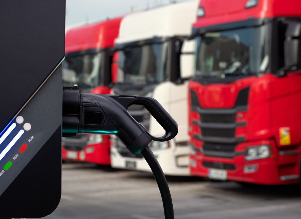
Tark Thermal Solutions engineers cable and connector cooling units to the specific packaging, duty, and environmental constraints of each platform. The following inputs allow a first pass sizing and a credible quotation.
Thermal and electrical duty
| Input | Why it matters |
|---|---|
| Continuous and peak cable current (A) | Sets the I²R heat load, the single most important input |
| Duty cycle | Session length, interval between sessions, and expected site utilization; determines whether the unit is sized for peak or sustained load |
| Cable length and conductor cross-section | Together these set cable resistance and therefore total heat generated |
| Number of dispensers sharing the cooling infrastructure | Determines whether a single unit serves one cable or several |
| Maximum allowable connector and handle temperature | Sets the required coolant flow rate and supply temperature and pressure for the required heat transfer |
Packaging and integration
- Available volume and mounting envelope for the cooling unit, with orientation constraints
- Available airflow at the heat exchanger, free-breathing, ducted, or shared with power-electronics cooling
- Coolant loop topology, local in the dispenser, or remote in the power cabinet with hose run length
- Interface requirements, hose sizes and fitting types, electrical supply, communication bus
Environment and compliance
- Ambient temperature range and whether solar loading applies
- Noise limit in dB(A) and the measurement distance it is specified at
- Required IP and IK ratings
- Applicable safety, EMC, and regional certification standards
- Coolant medium — water-glycol or dielectric oil, and any customer-mandated fluid specification
Planning
- Target production volume and ramp schedule
- Required sample and qualification timing
- Service model — planned coolant intervals, field-replaceable items, expected station life
If current, duty cycle, cable geometry, and available volume are known, a first-pass capacity and envelope assessment is possible without a formal RFQ. Where packaging is tight or the duty cycle is unusual, thermal simulation and prototype validation are part of the development program rather than an add-on.
Contact us TO DISCUSS YOUR SPECS >>
Frequently asked questions
At what power level does an EV charging cable require liquid cooling?
Liquid cooling becomes mandatory for EV charging cables above approximately 400 A, roughly the point where chargers exceed 300 kW. Below that current, passive or forced-air cooling of a compact cable and connector assembly can be sufficient.
How much cooling capacity does an EV charging cable need?
A typical cable and connector cooling unit is designed for 1–3 kW of cooling capacity, rising to approximately 5 kW for continuous-duty and MCS applications. This is far below the charger's kW rating because only resistive losses in the cable and connector — not the delivered power — must be removed. A 1 MW charger may require only a few kW of cable cooling.
Why can't you just use a thicker cable instead of cooling it?
Reducing resistance by increasing conductor cross-section works electrically but fails ergonomically. A cable sized to carry 500–700 A without cooling would be too heavy and too stiff for an operator to handle repeatedly. Liquid cooling exists to keep the cable thin and flexible at high current.
What coolant is used in liquid-cooled EV charging cables?
Water-glycol in a closed loop is the mainstream coolant for passenger-vehicle HPC and heavy-duty truck cables at 500–700 A. Dielectric oil is the alternative where higher cooling capacity is needed, since it can directly contact energized conductors — at the cost of harder sealing, material compatibility, and environmental compliance requirements.
What flow rate and pressure does an EV charging cable cooling system use?
Typical parameters are 2–3 L/min coolant flow at 1–4 bar operating pressure.
What environmental ratings apply to EV charging cable cooling systems?
IP54 to IP56 for dust and water ingress, IK10 for mechanical impact (20 joules, per IEC 62262), operation from −30 °C to +55 °C, and acoustic emissions at or below 65 dB(A), plus vibration and salt-spray resistance.
How long do EV charging cables and cooling systems last?
Charging stations are expected to operate for more than 10 years. Cable sets are typically rated for approximately 10,000 plug cycles. Cooling systems should be specified to exceed station life without oversized pumps or heat exchangers.
What is the difference between CCS and MCS for cable cooling?
CCS operates up to 1,000 VDC and 500 A, and covers passenger EVs plus most of today's heavy-duty truck charging. MCS allows up to 1,250 VDC and 3,000 A and is purpose-built for heavy-duty vehicles. MCS drives substantially higher heat rejection at the connector and often requires multi-loop or dielectric cooling.
Do EV charging cable cooling systems support predictive maintenance?
Deployed charging infrastructure does not yet use predictive maintenance. Sensor-rich cooling systems with temperature, flow, and pressure monitoring over CAN bus, with OCPP 2.0.1 readiness, provide the data foundation for condition-based service; currently a point of differentiation rather than a market standard.
How does the split-cabinet charger trend affect cable cooling?
Split-cabinet designs move power electronics into a central cabinet to keep dispensers slim. This raises power density and eases serviceability, but leaves less enclosure volume and airflow in the dispenser for the cable cooling heat exchanger; making compact, high-capacity cooling units more critical, not less.